Designing a Multispectral Payload for Lightweight Drones
Work in progress, this post is currently being written and will be completed soon.
Context
This is a continuation of the work I’ve been doing around the small flying wing I shared earlier. The idea is to explore how far I can push that platform, not just flying for flying. I want to embark intelligence, more precisely, for trying to detect things on the ground that might not be visible in normal RGB imagery. Stressed vegetation, early signs of erosion, or in land use. I don’t know yet how far this can go, but I wanted to see if it’s at least possible to startchanges.
Acknoledgement
I came up with this project idea and started building the first prototype before doing any literature review (I know bad practice but I’m not really aiming for academical). Later, while looking into similar works, I found out that low-cost dual-band multispectral systems have already been explored in research contexts. In particular, I’d like to mention the works by Cañada et al. (2020) on Raspberry Pi-based NDVI systems, and other experiments combining OV5647 modules. These studies confirm the feasibility of the approach, and they helped me validate some of the technical choices I had made independently.
This project doesn’t aim to improve on those works directly, but to take the idea into a new direction: lighter, fully embedded and edge processed.
How it started
The first thought was just to mount a single camera pointing down and do some basic analysis onboard. But that quickly ran into limits. If I want to detect subtle changes, like dry vs. healthy vegetation, RGB isn’t enough. I started looking into multispectral setups, and that’s where things got complicated. True multispectral sensors are out of reach for this kind of project, both in cost and in integration complexity.
So I began thinking low-cost, trying to see if I could get meaningful spectral separation by using different filters in front of standard sensors. I settled on a basic configuration: three identical camera modules, each with its own optical filter: one for visible light, one for red, one for near-infrared. The filters are integrated into M12 lenses, which simplifies the build and keeps things lightweight.
Hardware Direction : Low Cost COTS
Sensors and Filters
OV5746
The OV5647 is natively supported by the Raspberry Pi ecosystem, with robust Linux drivers and extensive community documentation. Its popularity in both hobbyist and research projects means there is a lot of publicly available analysis, including detailed spectral response data. In addition it is available in NoIR version, i.e, without any IR-cut coating that would jeopardize the project (we need the near infra red band !).
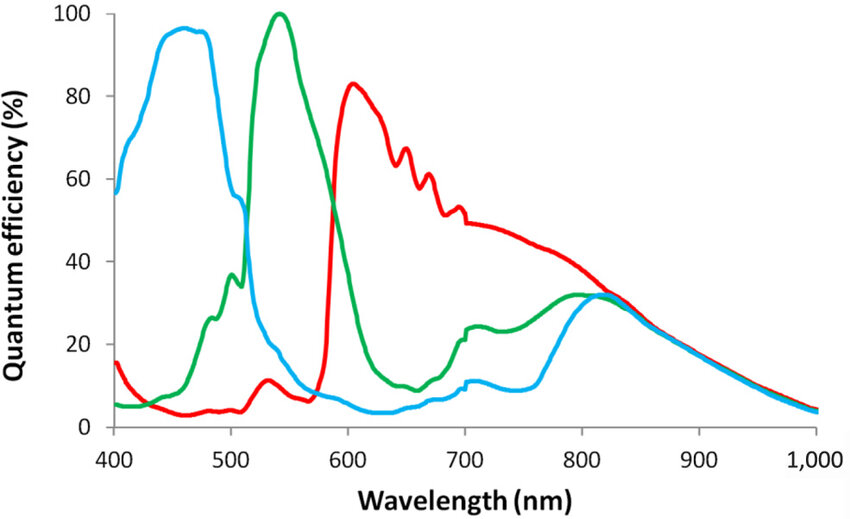 Analytical Spectral Response of OV5647 from 10.1108/SR-12-2016-0276
The spectral response of OV5647 clearly shows that the sensor can be used to capture both RED and NIR bands up to around 900 nm efficiently.
Optical Filters
As explained earlier, the OV5647 sensor comes without any built-in filters, so it captures a wide range of light—from below 400 nm to above 900 nm (near-infrared). To analyze specific bands, we need to separate the light into the regions we care about. The best way to do this is by using optical filters that only let certain wavelengths through.
I chose to use M12 camera lenses with integrated optical filters. Each lens has a different filter: one passes only visible light (we wont use it because of hardware limitations), another passes red light (around 650 nm), and the third passes near-infrared light (around 850 nm). By mounting these filtered lenses on identical camera modules, each sensor captures a different part of the spectrum. This setup is simple, lightweight, and keeps the hardware cost low, while still allowing us to collect the data needed for multispectral analysis.
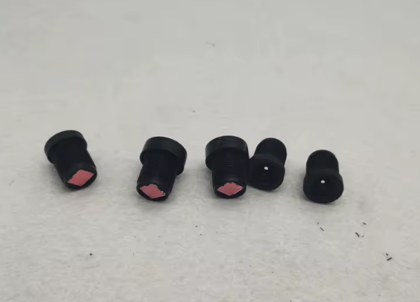 Lens with integrated filters : Visible, Red (650nm) and Near Infrared (850nm)
Onboard Computer (OBC)
At this point it was clear I couldn’t use a Raspberry Pi or similar single-board computer: they only support one camera natively. I could have tried stacking several, but it didn’t feel sustainable or clean. So I shifted to a SoM-based (System on Module) approach, specifically the Raspberry Pi CM5. It gives me access to multiple CSI interfaces and is compact enough to integrate into the airframe. I’m now working on designing a minimal carrier board that can host the CM3 and connect three CSI cameras directly, with synchronized triggering and clean power management.
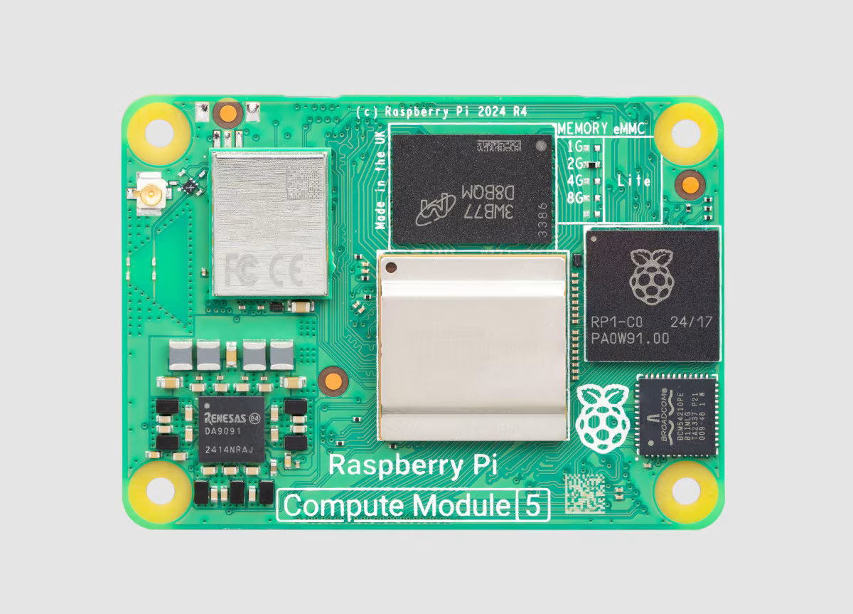 RSoM
RSoM
One of the big advantages of using a System on Module (SoM) like the Raspberry Pi CM5 is flexibility. Unlike a typical single-board computer (e.g., Raspberry Pi) a SoM lets you design your own base board to fit exactly what you need. The advantage is freedom, the drawback is you: you’re the designer, so every problem is now your (my) problem !
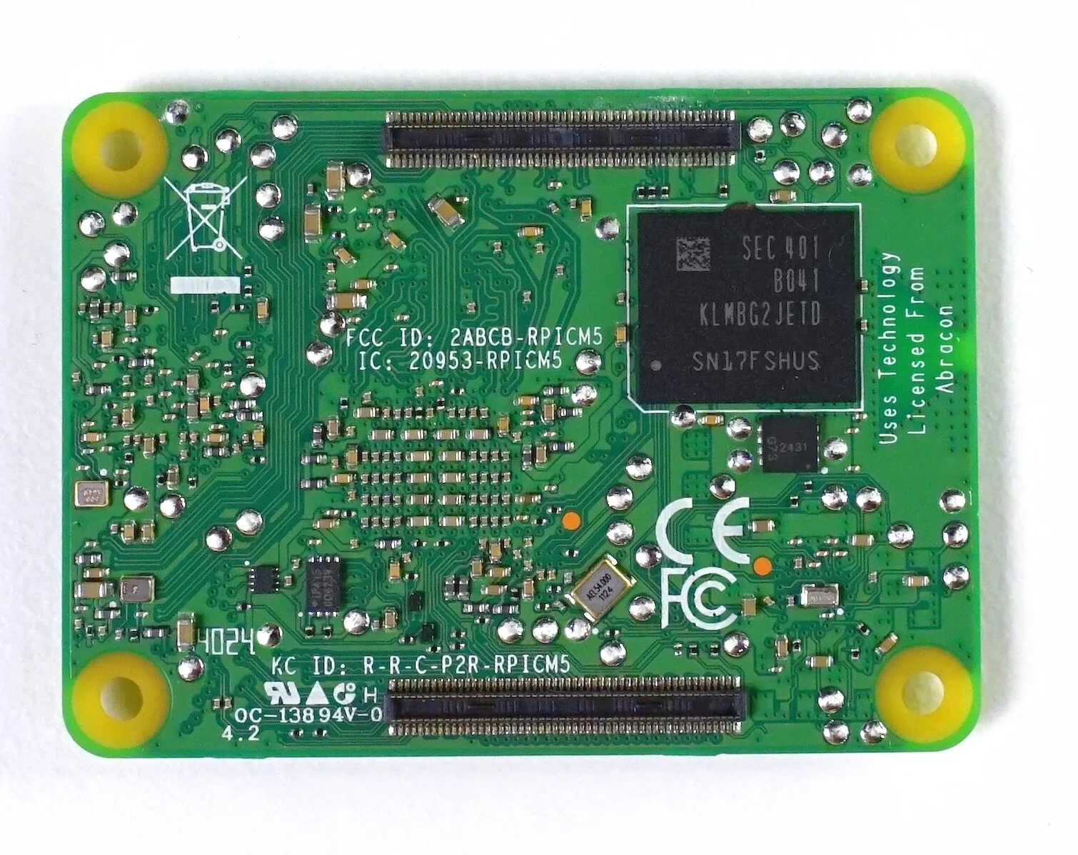 CM5 Back with interfacing Hirose DF40C-100DP-0.4V(51) dual connectors
However, the CM5 only has two CSI camera inputs. This means I had to reduce the setup from three cameras to two: one for RED and one for NIR. By using a dual-band configuration, it is still possible to calculate useful indices like NDVI (Normalized Difference Vegetation Index):
CM5 Back with interfacing Hirose DF40C-100DP-0.4V(51) dual connectors
However, the CM5 only has two CSI camera inputs. This means I had to reduce the setup from three cameras to two: one for RED and one for NIR. By using a dual-band configuration, it is still possible to calculate useful indices like NDVI (Normalized Difference Vegetation Index):
NDVI = (NIR - RED) / (NIR + RED)
Hardware Dev Platform and System Performance
Hardware Setup: CM5 and IO Board
I received the Raspberry Pi Compute Module 5 (CM5) along with the official IO Board for development. The IO Board makes it easier to test and develop on the CM5: it gives access to USB, HDMI, CSI, and power without designing a custom carrier board yet.
I flashed the 32 GB eMMC on the CM5 with Raspberry Pi OS Lite (64-bit). I chose the Lite version because it has no desktop environment and uses less memory. It’s better suited for embedded use where I want to run only what’s needed, nothing more.
After flashing, I connected via SSH over Wifi and started configuring the system for headless operation and testing.
System Performance
Before building the full image processing pipeline, I tested the onboard compute module (Raspberry Pi CM5 – 4 GB RAM, 32 GB eMMC) to get a better sense of what it can handle in terms of CPU and memory performance.
I used sysbench to simulate realistic workloads. For CPU, the system completed over 10,900 operations per second using all four cores. For memory, the measured bandwidth was 3650 MiB/sec, which is far beyond what I need for two image buffers and spectral calculations.
Temperature under load stayed very low, around 42.8°C, with no active cooling. This is well within thermal safety margins for a sealed, embedded application.
To simulate image processing, I ran a JPEG compression on a 1920×1080 grayscale image using ImageMagick. It completed in 52 ms, which means I can easily process and save frames at around 10 Hz if needed.
These results confirm that the CM5 has more than enough capacity for real-time multispectral capture and analysis, even with basic image alignment and NDVI computation onboard.
Designing the Onboard Intrument Computer
There are still a lot of open questions. I’m not sure yet how well the image alignment will hold in flight. I ordered the components and will begin testing upon delivery. But the general structure is there, and I think it’s worth trying.
For now, I’m mostly trying not to go insane while designing the OBC PCB, there’s just so much documentation, so many pins, and a maze of standards to keep track of. But I’m here for this !
The goal isn’t to match what professional multispectral payloads can do it’s to see whether something simpler and cheaper could still be useful. If I can fly, capture all three bands, align them well enough, and compute something meaningful on board that will already be a great achievement !
Notes on Designing The Multispectral Carrier Board for the CM5 (to be organized)
Using Two Cameras on the CM5
The CM5 exposes two CSI interfaces: DPHY0 and DPHY1.
- CSI0 (DPHY0) is the primary interface. It uses
SCL0/SDA0(I²C0) and exposesCAM_GPIO0andCAM_GPIO1by default. These are used for reset/power control of the camera. - CSI1 (DPHY1) is the secondary interface. It does not expose dedicated GPIOs, so I had to assign my own GPIOs for reset and power control.
I connected one OV5647 camera on CSI0 (simple, well-documented), and another on CSI1, using ID_SC/ID_SD (I²C1 or i2c_vc), with custom GPIOs for control.
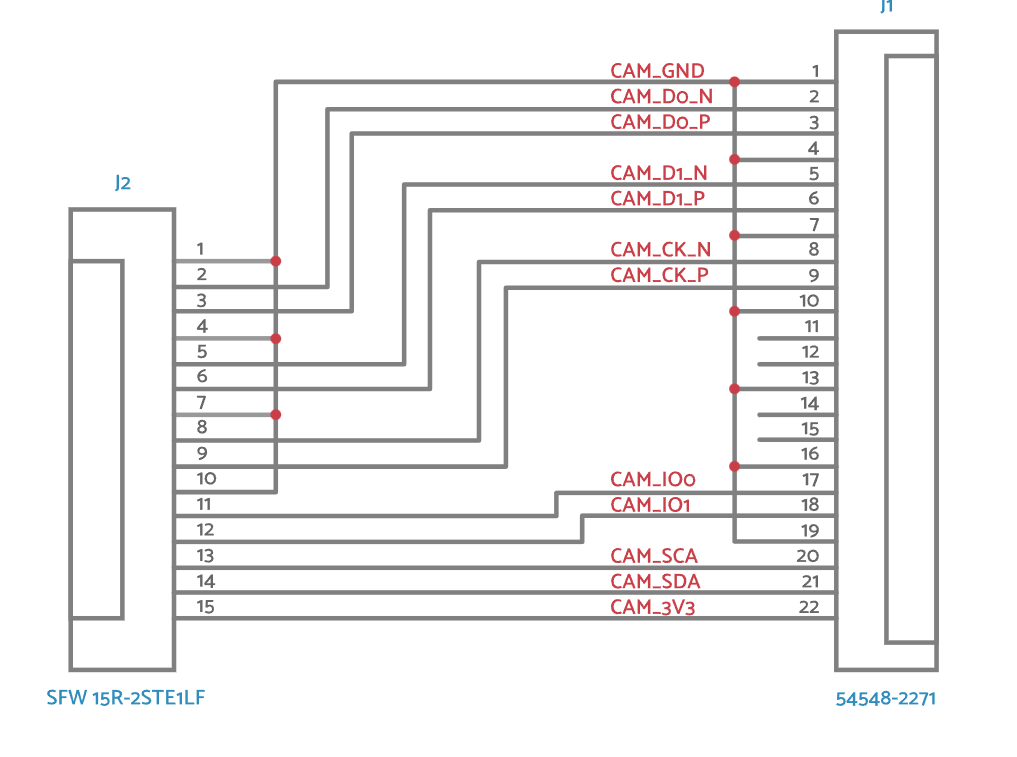
Connector Choice: 15P vs 22P
At first, I considered using 15-pin FFC connectors for the cameras, because that’s what most Raspberry Pi cameras (like the OV5647 or HQ Camera) use. However, I quickly realized that 15P is a legacy format:
- Limited to 2 CSI data lanes (not scalable for high-res or 4-lane cameras).
- No room for D2/D3 lanes, which limits future compatibility.
- Less differential pair symmetry and grounding.
So I switched to using 22-pin CSI connectors, like the official CM IO boards. These support 4 data lanes, better signal integrity, and GPIO+I²C breakout.
To connect standard 15P cameras to my 22P connectors, I used FFC 15→22 adapters, which are widely available and match the official RPi wiring.
Choosing GPIOs for the Second Camera
Since only CSI0 has CAM_GPIO0/1, I needed to assign GPIOs for the second camera (CSI1) manually. I chose GPIO26 for RESET and GPIO27 for PWDN. These are available, not reserved, and safe to use.
In the device tree, I will map them like this:
reset-gpios = <&gpio 26 GPIO_ACTIVE_LOW>;
pwdn-gpios  = <&gpio 27 GPIO_ACTIVE_HIGH>;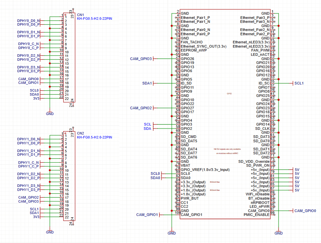
I²C Bus and 5V Safety
Here’s the most important lesson I learned: Never trust that an I²C module is safe to connect directly to a Raspberry Pi.
I connected an IMU module (LSM6DS33) to GPIO2 (SDA1) and GPIO3 (SCL1). It worked, but I later found that the module has pull-ups to 5V (VIN) on SDA/SCL. That’s a problem.
The CM5 GPIOs are 3.3V-only. Applying 5V via pull-ups can stress or damage the SoC’s internal ESD protection diodes. While 10kΩ resistors limited the current to ~170 µA and avoided instant failure, this is still out-of-spec and risky.
I powered the module with 3.3V, this restored safe operation.
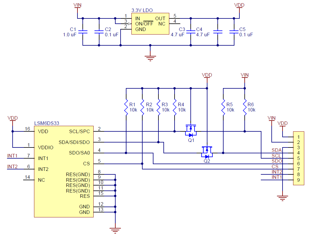 LSM6DS3 Module With Exposed 5V Pull Ups
Check list
- Always inspect schematics of modules — never trust that I²C pull-ups are “safe”.
- Avoid 15P CSI if you want future-proofing. Use 22P.
- Always assign clean GPIOs for camera control.
- CSI1 is usable with proper I²C and GPIO mapping.
- Raspberry Pi GPIOs are fragile: never put 5V on them.