Thrust Vectoring Study and Prototype
Project Overview
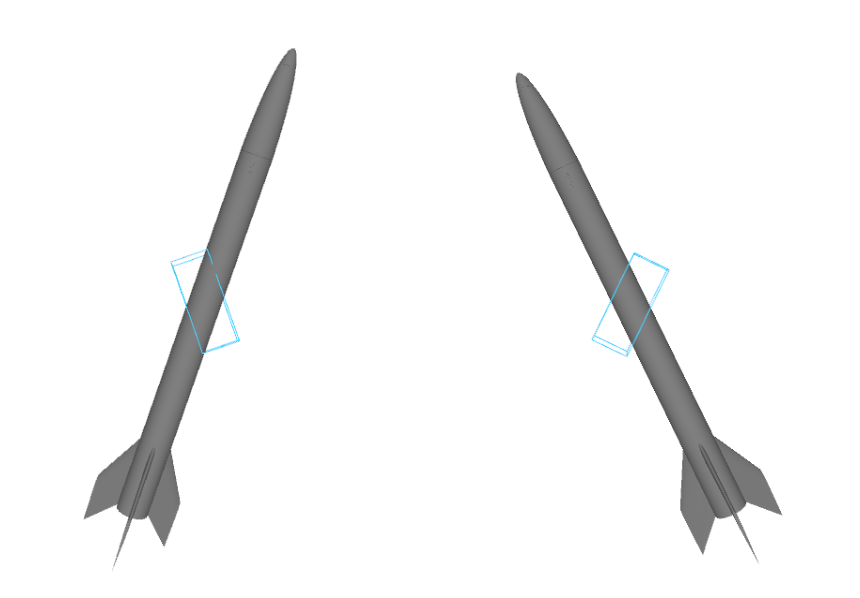
This project was developed during my second year at the University of Limoges (DUT GEII). Together with a friend, we built a working prototype of a Thrust Vectoring Control (TVC) system for a model rocket using solid fuel. Our goal was to actively steer the rocket during its short burn phase (~2.2 seconds), instead of relying only on passive fins.
We integrated real-time sensors, a custom-built control system, and several simulation tools to design and test the flight behavior. The project combined electronics, embedded programming, control theory, and physical modeling under tight constraints of time, weight, and power.
Why Thrust Vectoring?
In most amateur rockets, fins provide passive aerodynamic stability. But they can’t react to disturbances during the burn phase, and they can’t adjust trajectory. We wanted to see if we could implement an active control system, like those used in real aerospace vehicles, to steer the rocket by orienting the motor’s thrust vector.
System Architecture
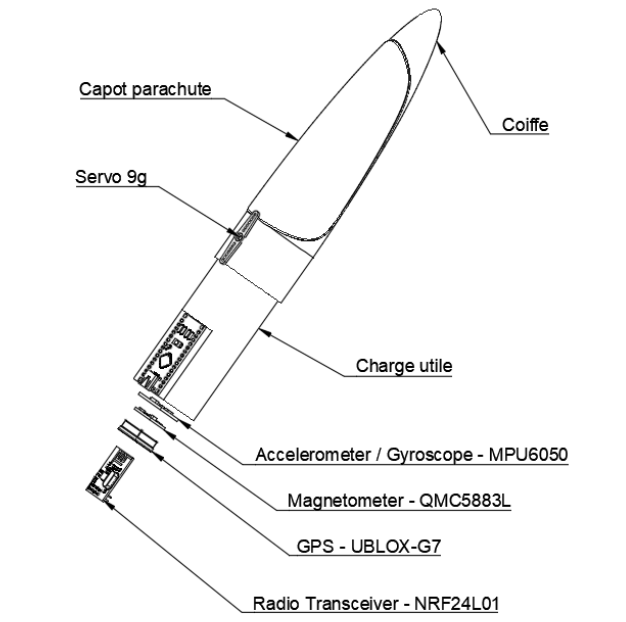
We designed a modular system including:
- Arduino Nano as the central controller.
- IMU (MPU6050 + QMC5883L) to measure roll, pitch, and yaw.
- TVC Module using two micro servos to tilt the motor in two axes.
- Automatic parachute deployment system triggered by servo.
- OLED screen to display system status pre-launch.
- NRF24L01 radio to send real-time data during flight.
- GPS module to locate the rocket post-flight.
- Processing-based 3D visualization for debugging and real-time monitoring.
All modules were designed to be lightweight and low-power to fit the constraints of a small rocket.
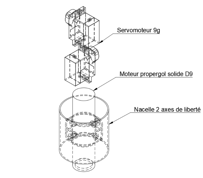
Thrust Vectoring Module
The TVC mechanism used two 9g servos mounted in a gimbal configuration to control the motor orientation. By measuring angular deviation with the IMU, the Arduino calculated small corrections to stabilize the rocket.
This was a basic control system, not a full PID loop.
We also implemented low-pass filtering to smooth the IMU data, reducing the effect of noise and vibration without making the system too slow.
Orientation Measurement (IMU)
We used the MPU6050 (accelerometer + gyroscope) and the QMC5883L (magnetometer) to estimate the rocket’s orientation:
- Roll and pitch were computed from accelerometer data.
- Yaw was derived from the magnetometer.
- All angles were filtered using a moving average to reduce noise.
Careful sensor placement was essential to ensure alignment with the rocket’s axis and avoid drift or misreadings.
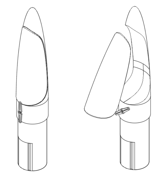
Parachute System
A servo-controlled mechanism released the parachute at apogee. The system was designed for maximum reliability: one simple moving part, spring-loaded, released only when the servo moved.
Real-Time Monitoring
Before flight, we displayed system status on a small OLED screen.
During flight, we transmitted telemetry using NRF24L01 modules, which allowed us to receive orientation data in real time.
We built a Processing app to display the rocket in 3D using live data. This helped during testing and debugging.
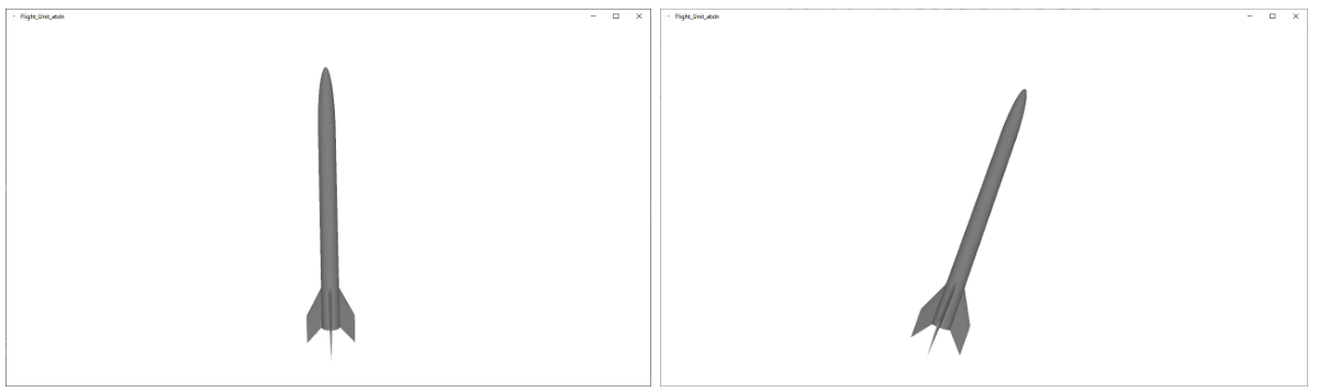
Simulations and Modeling
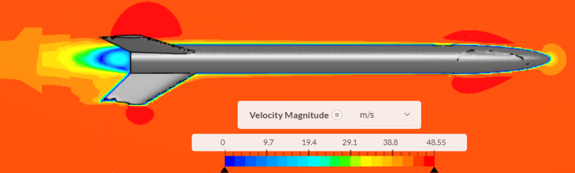
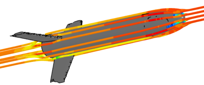
We used OpenRocket to simulate trajectories and tune mass, fin size, and center of pressure.
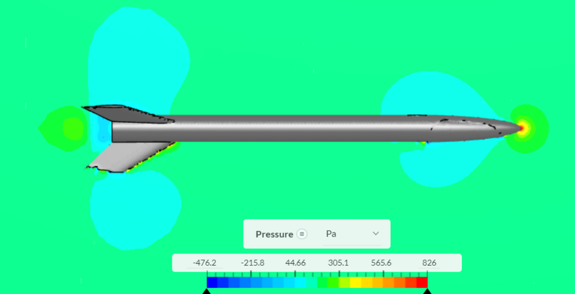
We also used Fusion 360 and SimScale (CFD) to model airflow and detect pressure instabilities. These simulations showed that the rocket’s nose and parachute housing introduced asymmetric drag, justifying the need for TVC correction during flight.
GPS Tracking
The U-Blox GPS module provided post-flight location data. We decoded NMEA RMC strings to extract latitude, longitude, and speed.
Despite testing indoors during some tests, the GPS accuracy was within ~2 meters.
Results and Lessons
This was our first experience with real-time control on an embedded system. We succeeded in building a complete prototype. At the time, I had very limited knowledge of advanced control theory techniques such as PID controllers or Kalman filters. Most of the control logic was implemented using basic feedback and simple filtering.
Main challenges:
- Extremely short time window (2.2s of thrust)
- Mechanical limitations of hobby-grade servos
- Sensor noise and IMU drift
We learned a lot about embedded systems, control theory, signal processing, and multi-module integration under constraints.
What’s Next?
With more time and experience, we would:
- Replace basic filtering with a Kalman filter.
- Move to a real PID controller with dynamic gain tuning.
- Use faster actuators or gimballed motors.
- Log higher-frequency IMU data for better analysis.
- Test in more controlled outdoor conditions.
- MATLAB simulation driven design.