Smart Devices
Descriptive Part
AIME Lab Work
The gas sensor is a project we carried out over the course of a week at the AIME micro-electronics laboratory. The goal was to make a nanoparticle based passive gas sensor using micro-electronics technology available in the lab. The work implied the following steps:
- Synthetize the $WO_3$ nano-particules using basic chemistry
- Coating the poly silicon substract with photosensible resin to protect the useful circuit.
- Dip the subtract into acid to remove unwanted conductive parts of the circuit.
- Clean the subtract.
- Powder the subtract using electrophoresis with nano-particles and check that it is coated evenly on the conductive combs.
- Cut the individual silicon dices off the wafer.
- Wire bond the die to the package using ultrasonic bonding.
- Characterize the gas sensor resistance.
Microcontroller and Open Source Hardware (MOSH)
This project is the continuity of the work we achieved at the AIME lab concerning the nanoparticle gas sensor. The goal was to integrate the analog gas sensor into a complete embedded IoT system.
Sensors Introduction
The goal was to gain basic knowledge about different types of sensors (actives, passives) and how to implement/use them in a system.
Analog Electronics Lab
This part, like the MOSH was part of the continuity of the AIME work. The goal was to integrate the analog gas sensor into a complete analog chain for microcontroller integration.
Technical Part
AIME Lab Work
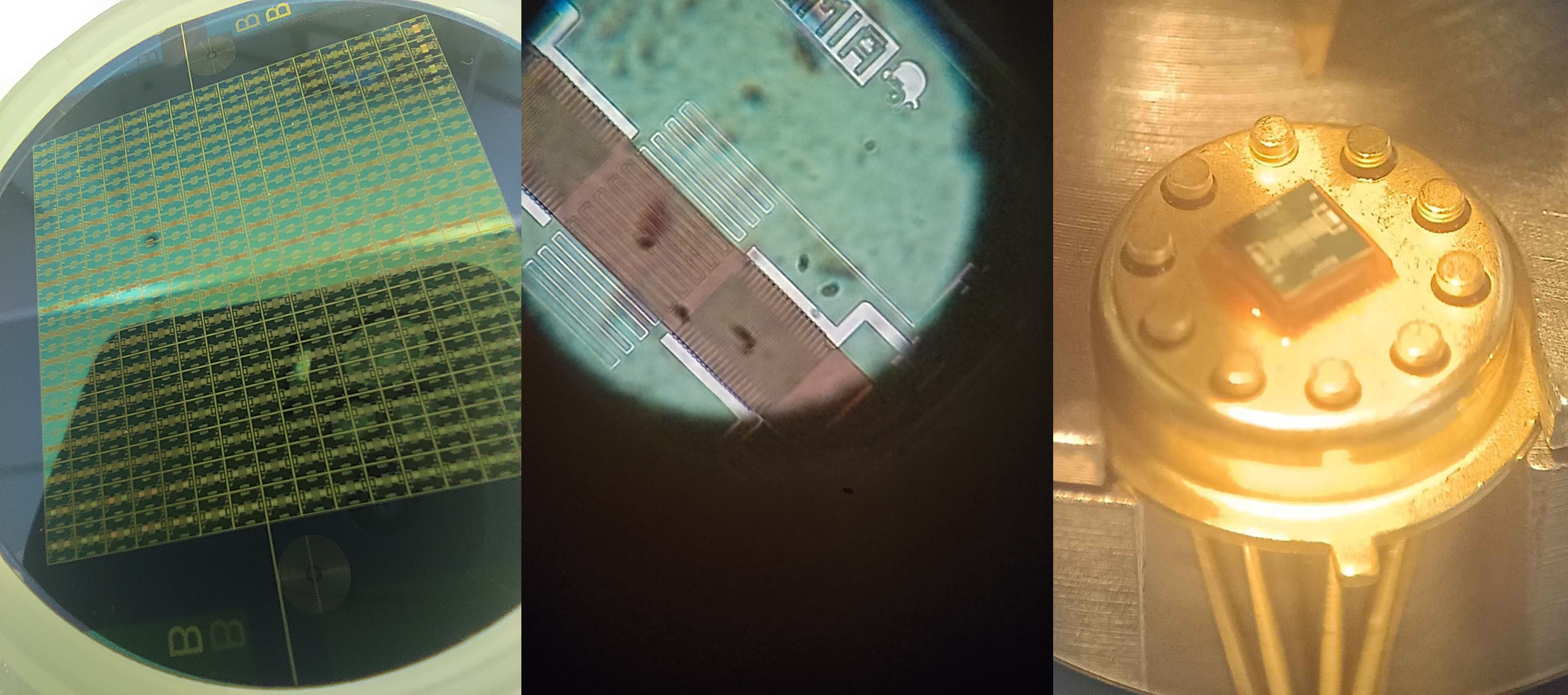 Image: From left to right: Silicon Wafer, Close up view of an interdigitated comb and close up view of the gas sensor die integrated in its 10 Leads TO-5 Metal Package
Analog Electronics Lab: Signal Conditioning for the Analog Gas Sensor
Gas sensor Characteristics
The gas sensor has an impedance of several gigaohms, requiring signal amplification. But amplification increases signal noise as well, hence the conditioning circuit needs several filters to improve signal quality:
- Filter for the high-frequency noise.
- Filter for the 50Hz outlet noise.
- Filter for the ADC sampling noise.
Amplifier Design
When designing the signal conditioning circuit two types of amplifiers were considered: a standard low-cost amplifier and a costly very low offset amplifier (LT1050).
We performed simulations on both and found that the LTC1050, better suited our application (as expected) because a high offset could significantly affect the accuracy of the gas sensor readings.
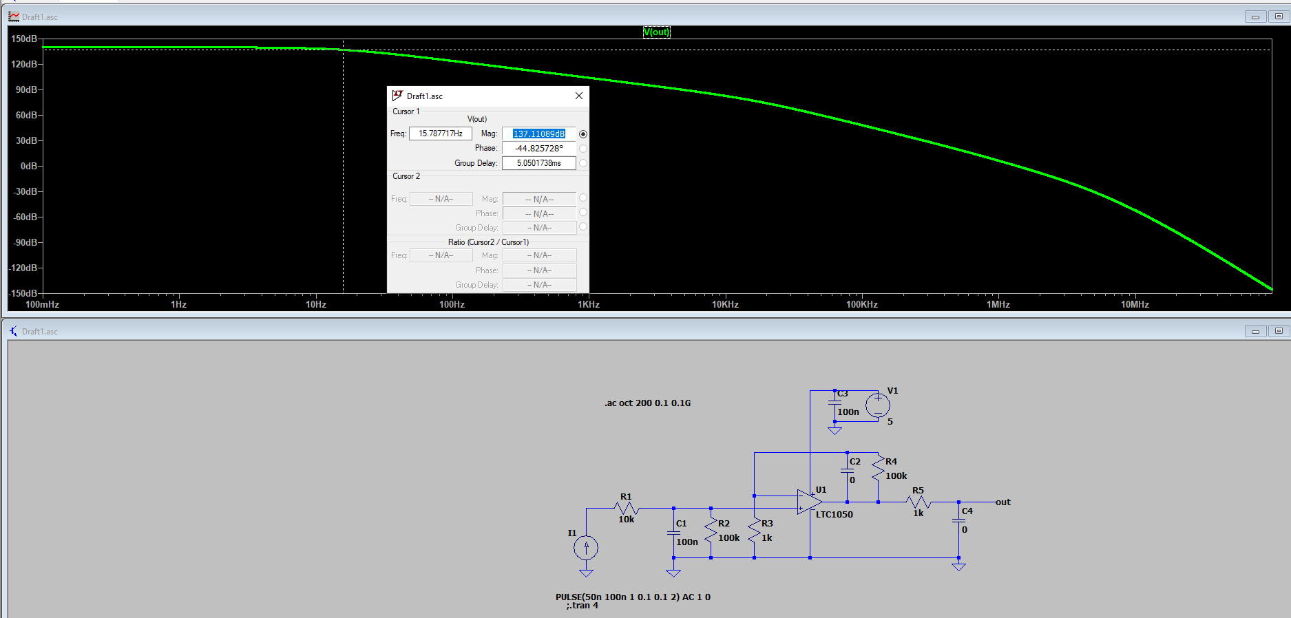
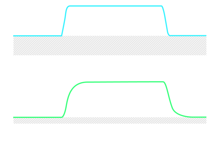 Image: LTSpice Simulation of the circuit comparing the two OpAmps
Filters Specifications
- First Filter: Cutoff frequency at 16 Hz.
- Second Filter: Cutoff frequency at 1.5 Hz.
- Third Filter: Cutoff frequency at 1.6 kHz.
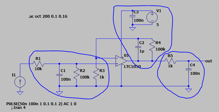 Image: LTSpice Schematic of the cirtuit with the 3 filters outlined in blue
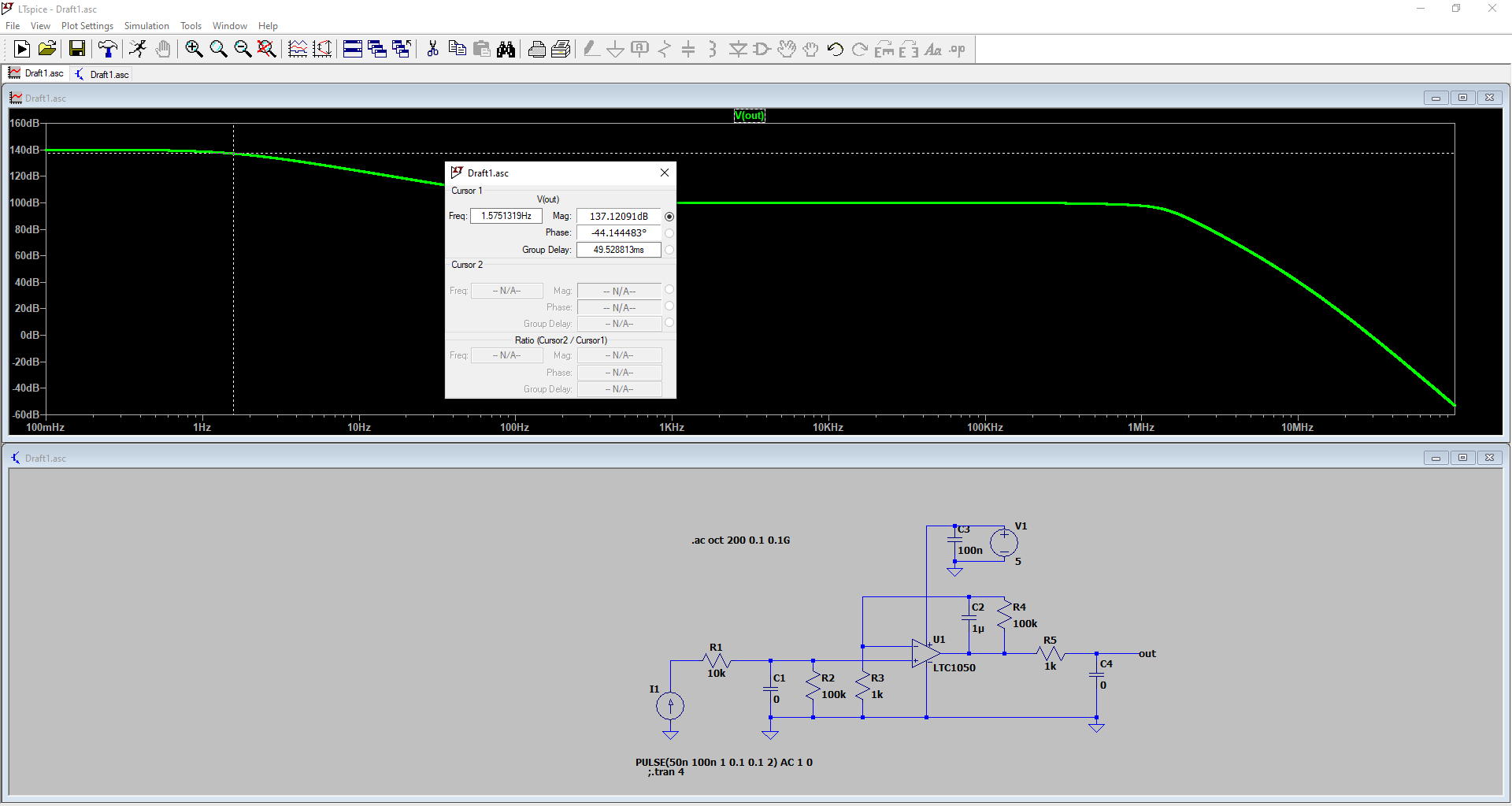
Filters LTSpice Simulations
Simulation of cutoff frequencies of the different filters:
- First filter: 16Hz
- Second filter: 1.5kHz
- Third filter: 1.6kHz
 |
 |
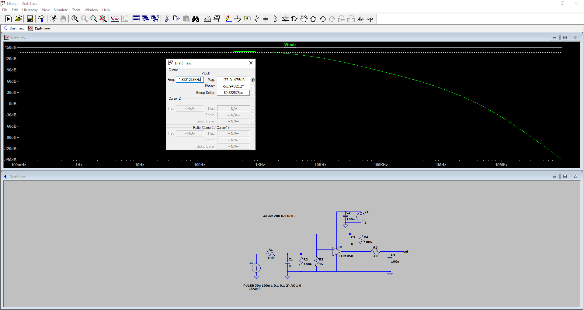 |
Click the Images to Zoom
Gas sensor model LTSpice simulations
In order to simulate the entire signal conditioning circuit, we needed an electrical model of the gas sensor, described as follow:
 Image: Gas sensor electrical model schematic
With the gas sensor modeled in LTSpice, we can integrate it into the complete conditioning circuit (amplification and filters) to perform simulations.
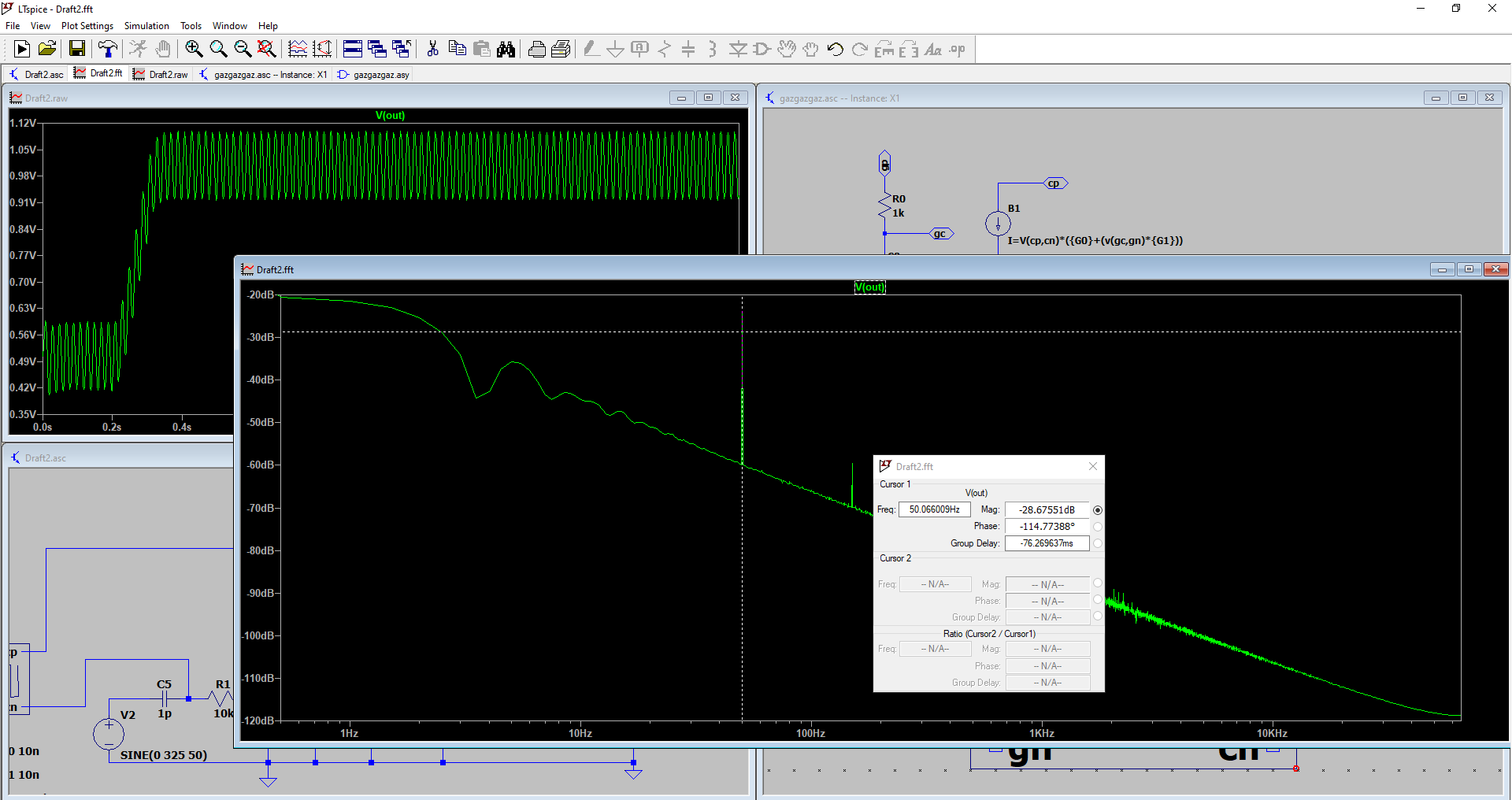 Image: LTSpice Simulation of the gas sensor model without 50Hz filtering
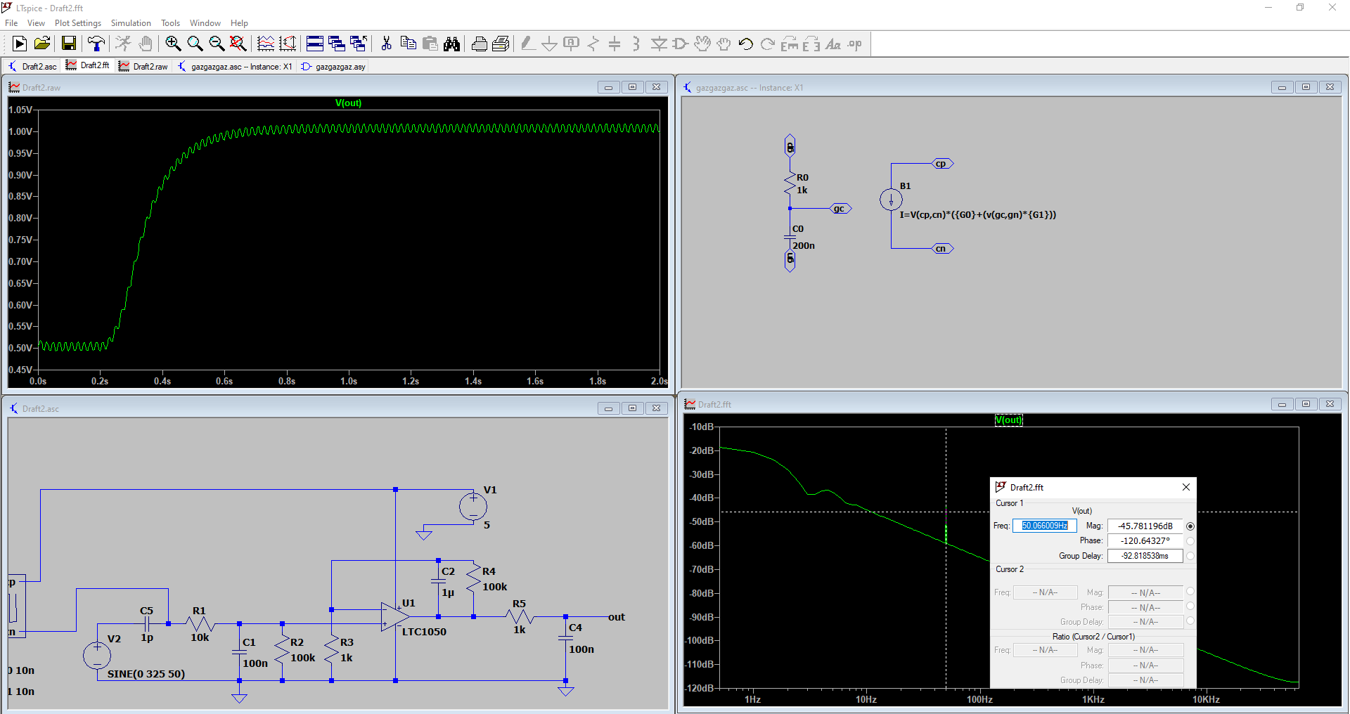 Image: LTSpice Simulation of the gas sensor model with 50Hz filtering
Based on the above-cited images we can clearly see why the filters (and particularly the 50Hz filter) are useful.
Microcontroller and Open Source Hardware (MOSH)
The goal is now to integrate the gas sensor into an IoT solution in order to provide useful information about air quality to users. We continue to build onto the previous tasks.
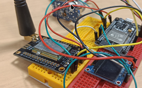
IoT Breadboard Prototype
 {: .center}
Images: Breadboard prototype including: ESP32, RN2483A LoRa Module, SSD1306 I2C Screen and MQ5 Gas Sensor
{: .center}
Images: Breadboard prototype including: ESP32, RN2483A LoRa Module, SSD1306 I2C Screen and MQ5 Gas Sensor
In this part, the goal was to:
- Integrate the gas sensor with the ESP32 (due to lack of time we integrated an off-the-shelf sensor but the principle is the same).
- Send sensor readings to Chirpstack via LoRa.
- Display information to the user directly on the device using an OLED screen.
As the gas sensor integration on the ESP32 is not extensively complex (ADC Reading) we will not cover it.
Chirpstack Integration using LoRa RN2483A UART Module
Chirpstack is an open source LoRaWAN Network Server stack that route and manages LoRaWAN data.
We used the following organisation:
- Integrate the LoRa RN2483A UART Module on the ESP32
- Configure the ESP32 to send data to the INSA LoRaWAN gateway
- Register to the INSA ChirpStack server
- Send sensor readings to the server and visualize it on the ChirpStack interface.
We had a lot of trouble sending data to ChirpStack server, here is a summary of the issues we faced:
- Erratic behavior (work 1/2 times) on damaged RN2483A module
- The RN2483A module did not work properly with the ESP32 at 3.3V, despite the datasheet indicating compatibility. It functioned correctly at 5V possibly due to a damaged module.
- While ChirpStack was configured correctly we faced issues with consistent data transmission because the INSA LoRaWAN gateway was saturated with traffic
- We spent a lot of time debugging on our side while the issue was out of our scope and our code was working properly.
After we found that the issue was not on our side we decided to focus on the part that we could control: reading/displaying data to user, developing the android application and working on the PCB Design (cf. next section).
Hardware PCB Design
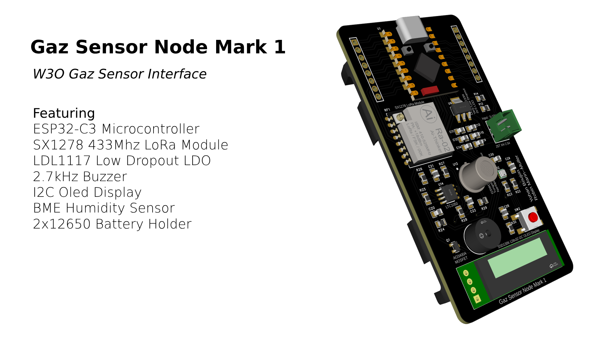 Image: 3D Render of the Gaz Sensor Integration Board
Specifications
As I was experienced with PCB design, we decided to directly dive into making the hardware based on what features we wanted:
- ESP32 based system (as we were at ease with the esp-idf framework)
- Gas sensor and conditioning circuitry
- SX1278 LoRa Module as we extensively used it in our innovative project
- LDL117 low dropout LDO to power the system efficiently on a single cell 3.7V LiPo battery
- A 2.7kHz buzzer to alarm users if gas levels are above a certain threashold
- The same SSD1306 I2C Oled Display that we used during the prototyping phase in order to diplay information to users locally
- A 12650 standard Li-Ion battery holder
- A button for easy mode switching and styreamlined user experience
- Bonus: BME MEMS Humidity sensor to provide additional metrics to the users.
Designing the Schematic
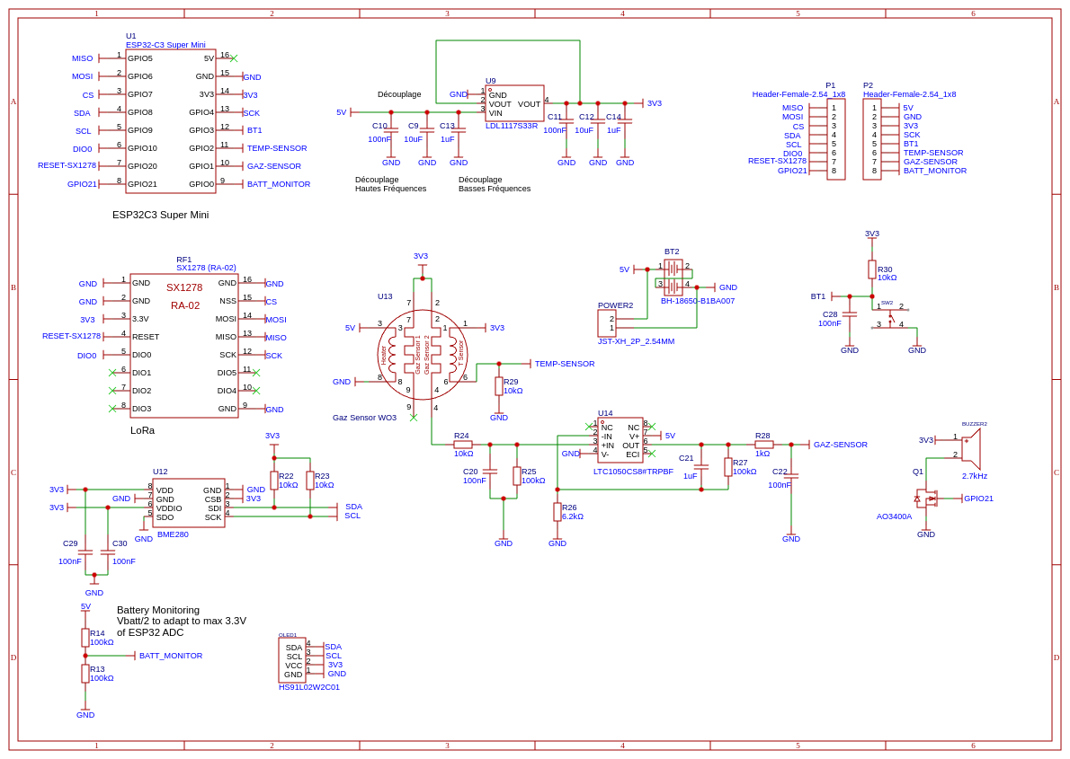 Image: Complete Schematic with all the Features Listed Above
To facilitate and accelerate schematic design, we chose components that we were already familiar with from past projects. This enabled us to skip some prototyping steps.
We also considered the assembly process during component selection, particularly focusing on component package types to ease the soldering process.
Routing the PCB
- ground and vcc plane
- dynamic track width
- thoughtfull component placement for easy soldering
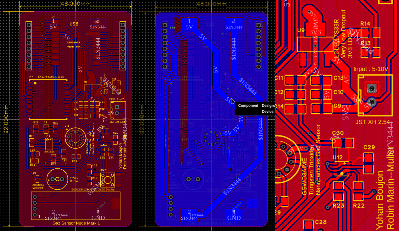 Image: From Left to Right: Top Plane, Bottom Plane and Focus on Dynamic Route Width
PCB Manufacturing
We manufactured the PCB using JLCPCB as I am very familiar with the platform. After two weeks we received the PCB and all the electronic components.
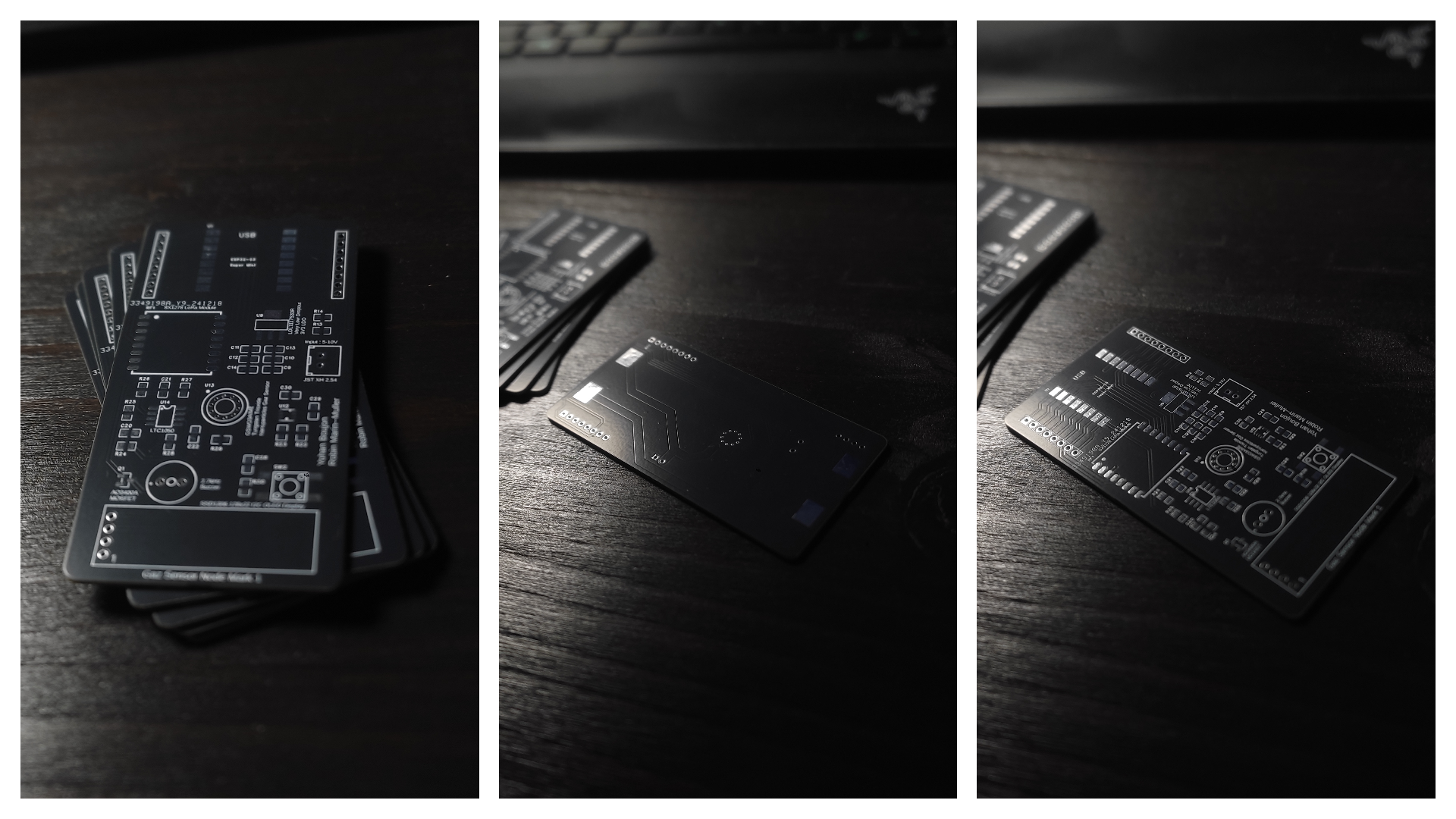 Image: Manufactured PCBs
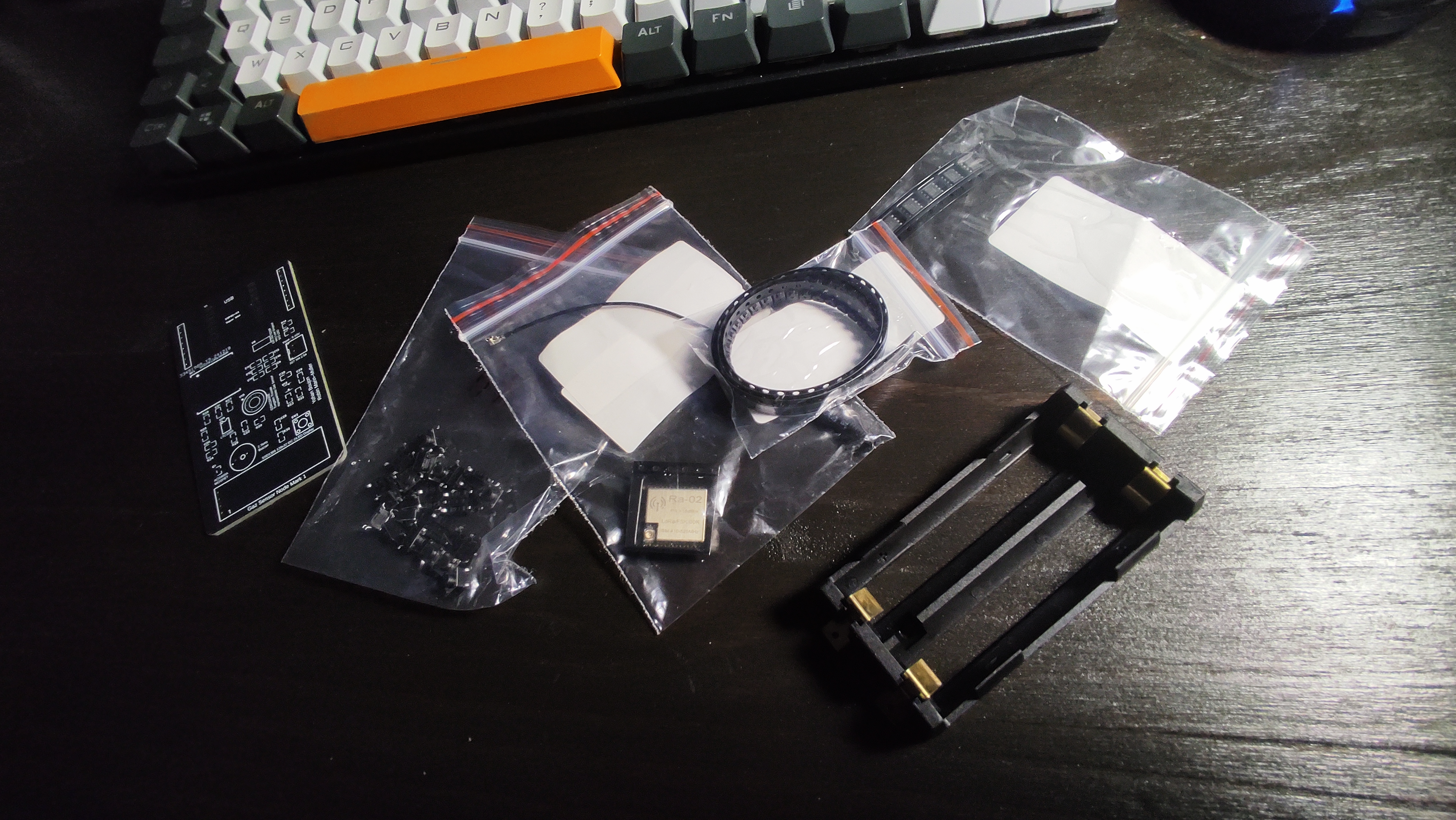 Image: Electronic Components
Due to lack of time, we couldn’t assemble the PCB during the project time. However, I plan to complete the assembly in my personal time because it was a very interesting project.
Analytical Part
AIME
Microelectronics has always fascinated me. The clean room practical lab was truly interesting, and I enjoyed every part of it. I learned so many things, from synthesizing nanoparticles to wire bonding the die to the package: we truly participated in all the major steps to create the gaz sensor, and this was rewarding. I really experienced what I had been learning in theory for years. This experience not only improved my understanding of the physical principles behind pretty much every modern objects but also lit up my curiosity to always know more.
Microcontroller and Open Source Hardware (MOSH)
I strongly believe that Open Source and Open Hardware is the key to achieving sustainability. Open Source allows accessible knowledge and accelerate innovation. Unlike proprietary solutions, Open Source gives everyone the tools to create, improve and share freely ensuring progress benefits everyone not just a select few.
In out interdisciplinary innovative project, I worked on a non-intrusive cutting edge water leak detection system. We choose to make this project fully Open Source, from the hardware design to the software source code: everything is accessible to anyone on GitHub. By sharing it openly we ensure and everyone (researchers, developers, students…) can build on top our work adapt it to their needs and create better solutions.
Isaac Newton once said, “If I have seen further it is by standing on the shoulders of giants.” What progress could he have made if science had been private and secret?
I strongly support Open Source because it gives people the ability to learn and take control of the technology they use. The Internet gave free knowledge to everyone; Open Source and Open Hardware is only the logical continuation of this philosophy. A philosophy in which I believe.
On the course side, it is quite obvious to remark that I trully appreciate the initiative to push Open Source on the front of the stage of this curriculum. but while I understand that not everyone comes from an electronics-oriented background, I would have liked to delve into more advanced topics. Nonetheless, I really enjoyed the course and took it as an opportunity to enhance my skills in microcontroller development and hardware design. The only aspect I found a bit frustrating was the inaccessibility of the INSA LoRa Gateway (overload in traffic I think), but that was beyond everyone’s control.
Electronic Lab and Sensors Introduction
The electronic lab improved my technical understanding of the gaz sensor we created at the AIME. The LTSpice simulations part was particularly interesting as we could see in a visual manner the electrical behavior of the sensor. Overall it was interesting.
For the Sensors Introduction course, it was a good refreshing lesson on metrology. As this was prior to the gas sensor integration, we could use what we learned effectively.
Skill Matrix
| Skills | AE | Evaluation method |
|---|---|---|
| Introduction to Sensors | ||
| Understand basic notions of sensors, data acquisition: physics, electronics and metrology point of view | 4 | Portfolio |
| Be able to manufacture a nano-particles sensor using micro-electronics tools: chemical synthesis, assembly, testing | 4 | Cleanroom training |
| Be able to design the datasheet of the sensor manufactured | 4 | Datasheet inserted in portfolio |
| Microcontrollers and Open Source Hardware | ||
| Understand microcontroller architecture and how to use them | 4 | Portfolio |
| Be able to design data acquisition system (sensor, conditioner, microcontroller) with respect to the application | 4 | Portfolio |
| Be able to design the electronic circuit of a sensor’s signal conditioner (design + simulation) | 4 | Portfolio |
| Be able to design a shield to accommodate the gas sensor | 4 | Portfolio |
| Be able to design the software to use the gas sensor and its HMI | 2 | Portfolio |
| Be able to combine all of the above mentioned components into a smart device | 4 | Portfolio |
1-level of application: follow-up of instructions or procedures
2-level analysis: improvement or optimization of solutions or proposals
3-level of control: design of programs or definitions of specifications
4-level of expertise: definition of guidelines or strategies
AE: Electronics/ Control